

Phone:
86-15852949220


Views: 10 Author: ALAS-MT Publish Time: 2024-02-08 Origin: Site
Hook: Choosing the incorrect press brake punch or die leads to immediate angular variation, surface gouging, machine tonnage overload, and premature tool wear.
Thesis: Selecting the optimal press brake tooling requires a systematic 5-step approach based on bending method, sheet material, part geometry, tonnage safety, and tool metallurgy.
Air Bending: The material touches only three points (the punch tip and two die shoulders). Offers high versatility and lower tonnage; the final angle is controlled by the depth of penetration.
Bottoming: The sheet is pressed fully into the lower die cavity. Requires 3x to 5x higher tonnage than air bending, yields tighter angular tolerances, and reduces material springback.
Coining: Extreme tonnage forces the punch tip to penetrate past the material yield point. Eliminates springback entirely, but drastically increases tool wear, scoring, and machine stress.
The 8T Rule for Mild Steel: For standard air bending of mild steel (thickness ≤ 6 mm), select a V-opening width (V) equal to 8 × material thickness (8T).
V-Opening Adjustments: Use V = 6T for tighter inner radii (requires higher tonnage) or V = 10T to 12T for thick plates, stainless steel, or high-tensile alloys (like Hardox) to prevent edge cracking.

The 16% Rule for Inner Radius (IR): Predict the final part geometry easily. In standard air bending of mild steel, the internal radius equals approximately 16% of the V-opening width (IR ≈ 0.16 × V). For stainless steel, the internal radius increases to roughly 20% of the V-opening due to springback variables.
Minimum Flange Verification: Ensure the workpiece flange spans at least 70% of the V-groove opening (minimum flange length ≈ 0.7 × V) to prevent the sheet from slipping into the die cavity during forming.
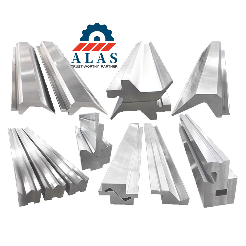
Straight Standard Punches: Ideal for simple 90° or shallow bends without return flanges.
Gooseneck Punches: Deep relief pockets clear returning flanges and narrow U-channel legs without tool-part collision.
Acute Angle Punches (30° to 60°): Required for pre-bending prior to hemming operations or for compensating for high-springback materials.
Sash / Narrow Window Punches: Specialized profile shapes for forming tight deep boxes or specialized electronic enclosures.
Calculate required tons-per-meter (T/m) for mild steel using the industry standard formula:
P = (650 × S² × L) / (1000 × V)
where P is Tonnage (Tons), S is Sheet Thickness (mm), L is Bend Length (m), and V is V-Opening Width (mm). Note: For Stainless Steel, multiply the final tonnage result by 1.5.
Tool Load Ratings: Always compare calculated tonnage against the maximum safe load rating (T/m) laser-etched on the tool body.
Avoiding Point Loading: Never concentrate high tonnage onto small, narrow tool segments without distributing the load or checking localized pressure limits.
Steel Grade Selection: Choose 42CrMo (AISI 4140) for high-precision, heavy-duty production; reserve carbon tools like T10 or T8 tool steel (AISI W1) for lighter-duty standard bending or flexible prototype work.
Heat Treatment Standards: Specify deep induction hardening across working radii (56 to 60 HRC at the tip, 47 to 52 HRC through-tempered core) to secure long service life and a factory precision ground tolerance of ±0.02 mm (±0.0008 inches).
Machine Compatibility: Match tool tang styles (European/Amada, Wila/Trumpf, American Tang, or LVD) and verify daylight/open height clearance.
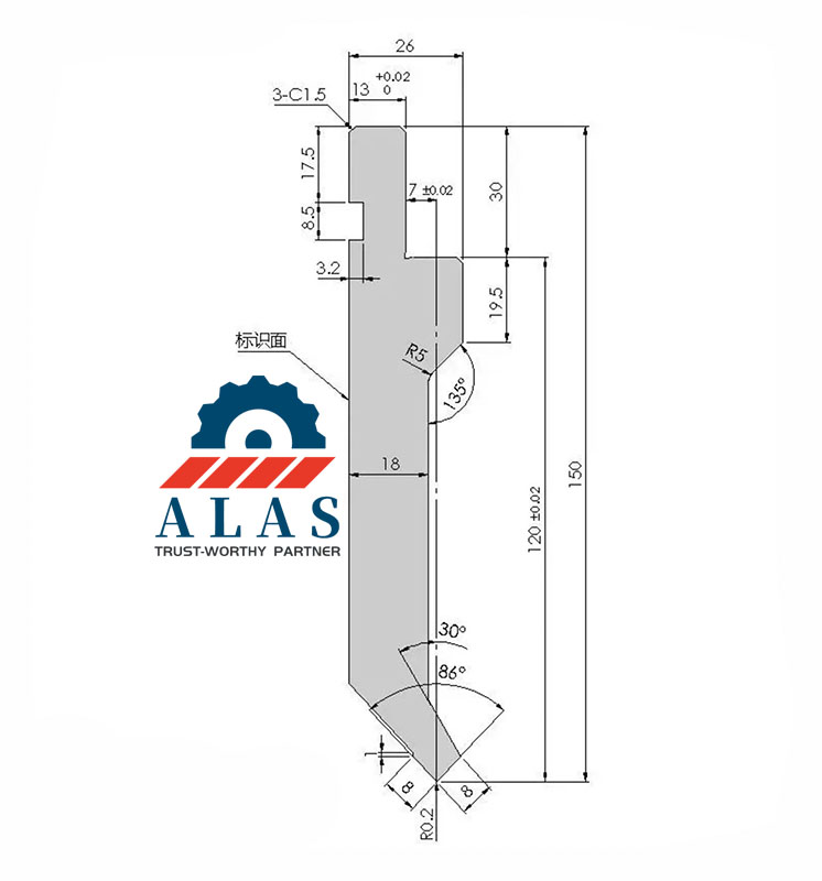
Need help selecting or calculating the exact punch and die setup for your press brake?
Contact the ALAS technical engineering team today for a FREE CAD drawing review and quote!
Nanjing Alas International Co., Ltd. is a professional industrial tooling manufacturer focused on shear blades, bending dies, shredder blades, and custom wear parts. We offer full application engineering, material selection, setup guidance, and after-sales support to global customers.
Tell us your requirements, and our engineering team will provide professional solutions for blade specification, tool life optimization, and cost-effective production.