

Phone:
86-15852949220


Views: 49 Author: Site Editor Publish Time: 2025-01-24 Origin: Site
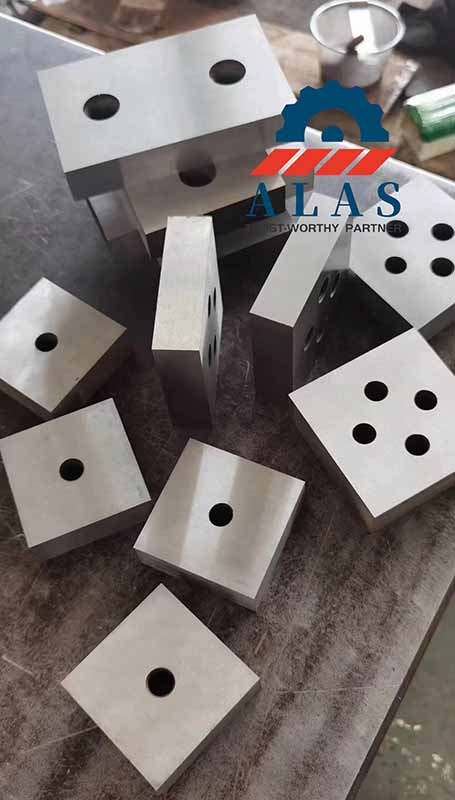
Dimensional Envelope: Standard square dimensions measuring 83×83×16 mm, 83×83×18 mm, 83×83×20 mm, or 90×90×18 mm featuring single-hole or double-bolt coordinate configurations.
Operational Capacity: Bounded strictly for light processing profiles and smooth plain carbon rounds below Ø25 mm, with a maximum machine capability up to Ø40 mm carbon steel.
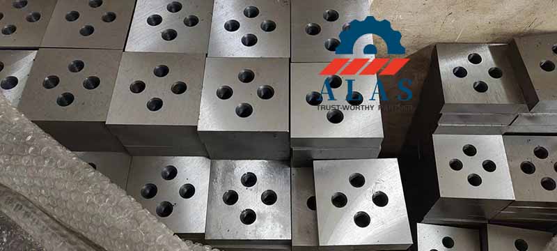
Dimensional Envelope: Heavy square dimensions measuring 90×90×20–26 mm or 100×100×20–28 mm utilizing double-hole or four-hole patterns. Note: The 90×90×26 mm square profile with a 4-hole pattern is the most common industry-standard configuration specified for high-frequency changeovers.
Operational Capacity: Engineered to process structural rods and deformed reinforcing bars up to Ø50 mm round steel (or Ø42–45 mm deformed structural steel rebar depending on specific hosting machinery configurations).
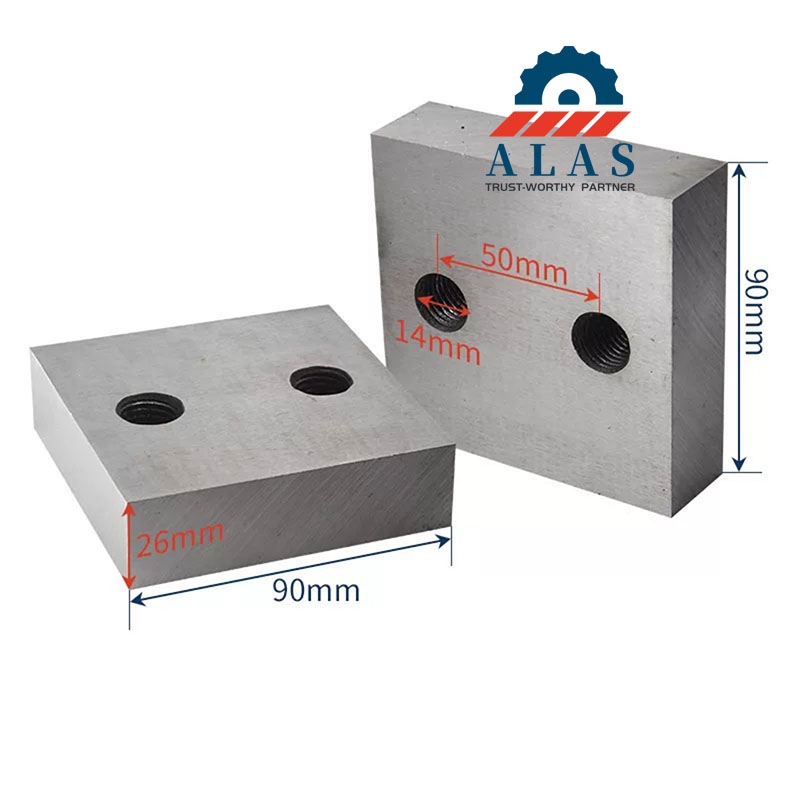
Dimensional Envelope: Heavy-duty structural dimensions up to 100×100×28 mm, 100×100×30 mm, or 130×130×30 mm featuring reinforced four-hole mounting layouts.
Operational Capacity: Specialized for high-tonnage heavy infrastructure field sites and scrap units processing large-diameter high-tensile bar feedstock from Ø6 mm up to Ø55 mm.
9CrSi Profile: Locked strictly at 55 to 58 HRC to secure optimal initial tool economy during low-volume standalone operations.
Cr12MoV Profile: Locked strictly at 58 to 60 HRC (with a maximum batch tolerance of ±1.0 HRC). This metallurgy provides continuous abrasive wear defense but is strictly restricted to uniform plant loading up to a conservative diameter of 32 mm or less to eliminate micro-chipping risks under dynamic loading.
Forged H13 Profile: Locked strictly from 50 to 55 HRC to utilize superior matrix fracture toughness, providing true kinetic impact absorption across the monolithic forging profile and preventing catastrophic tool block fracturing.
Thickness Red Line: Finished grinding thickness tolerance limits total dimensional variance strictly within ±0.1 mm to completely eliminate tool holder lateral play and prevent corner spalling during the shearing stroke.
Surface Alignment Profile: Linear parallelism and geometric perpendicularity must maintain a strict, uniform profile within ≤ 0.03 mm per 100 mm to distribute mechanical loading evenly across the tool seat.
Side Clearance Gap Non-Overlapping Settings: Direct lateral cutting clearance side gaps must be calibrated tightly via feeler gauges against the active feedstock diameter:
Ø6–20 mm Feedstock: Clearance gap must be dead-locked at 0.3 mm.
>20–32 mm Feedstock: Clearance gap must be dead-locked at 0.4 mm.
>32–55 mm Feedstock: Clearance gap must be dead-locked at 0.5 mm.
End-Face Quality Targets: Maintaining these strict tolerances guarantees an end-face shear inclination deviation within 1.5 degrees or less, successfully suppressing horseshoe deformation to clear obstructions for downstream mechanical sleeve splicing.
Step 1: Power Off and Lock Out: Shut down the main power supply and isolate the circuit breaker. Manually rotate the machine flywheel to verify that the blade holder has zero inertial movement and is completely stationary.
Step 2: Release Pressure and Debris: Open the hydraulic unloading valve (for fluid-driven models) to clear internal housing cylinder pressure. Remove the protective guards and clear accumulated metal scale, slag, and processing debris away from the tool seats.
Step 3: Standard Disassembly: Use specialized factory wrenches to loosen the blade fixing bolts in a strict diagonal sequence to prevent housing slot deformation. Steadily support the monolithic forging profile by hand and place the old blades in a non-slip recovery zone.
Step 4: Precise Installation and Gap Tuning: Fit the new matched pair of cutting edges flush against the positioning seat. Tighten the bolts diagonally with even torque. Use feeler gauges to fix the non-overlapping horizontal clearance gap exactly at 0.3 mm, 0.4 mm, or 0.5 mm depending on the upcoming feedstock batch diameter grouping.
Step 5: Reset Protection and Test Run: Re-lock the safety guards. Turn on primary line power and jog the equipment 2 to 3 times without load to track acoustic feedback. If the stroke is free from dragging or deep metallic squealing, execute a rebar test cut to verify normal line utilization.
Nanjing Alas International Co., Ltd. is a professional industrial tooling manufacturer focused on shear blades, bending dies, shredder blades, and custom wear parts. We offer full application engineering, material selection, setup guidance, and after-sales support to global customers.
Tell us your requirements, and our engineering team will provide professional solutions for blade specification, tool life optimization, and cost-effective production.