86-15852949220      mt@alasmachinery.com
NANJING ALAS INTERNATIONAL CO., LTD
You are here: Home » Products » Press Brake Tooling & Bending Dies » Heavy-Duty Press Brake Tooling for High-Tonnage & Thick Plate Bending

Product Category

Contact Us

loading

Share to:
sharethis sharing button

Heavy-Duty Press Brake Tooling for High-Tonnage & Thick Plate Bending

ALAS Heavy-Duty Tooling: High-Tonnage Press Brake Solutions
Heavy-duty press brake tooling and high-tonnage lower bending dies engineered for high-tonnage applications and thick structural plate steel fabrication., ensuring flawless angular accuracy during thick plate folding.
Key Features
High-Load Capacity: Handles 150T/m – 250T/m without deformation.
Deep-Hardened Radius: HRC 52–56 rating resists thick plate abrasion.
Reinforced Base: Widened shoulders and keyway locks prevent displacement.
Universal Match: Fits heavy Amada, Trumpf, Wila, and custom clamping.
  • ALAS

  • Nanjing, China

  • L/C, T/T, Paypal, Money Gram

  • Wooden Crate Packaging

Availability:
Quantity:

Ultimate Guide to Heavy-Duty Press Brake Tooling: From Advanced Metallurgy to High-Tonnage Selection

Choosing the right metallurgical composition for heavy-duty press brake dies is a pivotal decision that directly determines bending deflection limits, structural operational safety, and full-lifecycle production costs. Standard carbon steel is adequate for thin-gauge metal bending tasks, yet high-tonnage industrial scenarios require premium-grade alloy steels, primarily Cr12MoV and fully forged 42CrMo (4140).
For the processing of high-tensile steel plates and thick structural steel, ALAS provides upgraded premium tooling solutions, including 55SiCr and advanced surfacing-coated high-strength tool steels. These specialized materials feature outstanding compressive yield strength, exceptional wear resistance, and reliable anti-fatigue performance. Direct sourcing from manufacturers such as Nanjing ALAS Machinery ensures fully certified material grades and custom segmented dies that strictly comply with European, American, as well as Amada/Wila heavy clamping standards. This effectively cuts down frequent regrinding work, reduces mold change downtime, and extends the overall service life of tooling under extreme load conditions.

1. Why High-Tonnage Metallurgy Matters

In heavy-duty metal forming processes, punches and V-blocks are required to transmit enormous hydraulic pressure — often exceeding hundreds of tons per meter — to achieve precise bending angles. Any subsurface defects or poorly structured internal grain within die steel will inevitably cause structural warping, permanent angular distortion, or even sudden catastrophic die fracture under heavy loading.
Core Takeaway: Premium die metallurgy — achieved through strict ingot forging ratios, standardized uniform heat treatment, precise grain refinement control, and deep surface ion nitriding — directly governs tool service life, bending accuracy, and on-site workshop safety.

Heavy-Duty Bending Force Calculation Formula

P = (650 × L × t²) ÷ (V × K)

P = Required Bending Force (Tonnage, kN) 

L = Effective plate bending length (mm)

t = Workpiece thickness for heavy bending (mm) 

V = V-groove opening width of the bottom die (mm) 

K = Material property correction factor (compensates for material tensile strength and severe bending springback)

Key Operational Rules for Thick Plate Bending

V-Slot Scaling Rule: For thick plates with a thickness of 6mm or above, the conventional 8×t V-slot width standard shall be adjusted to 10×t or 12×t. This adjustment significantly lowers the required bending tonnage and prevents premature cracking on the shoulders of the lower die.
Tonnage Constant Explanation: The empirical constant value 650 is calibrated with field data for standard structural mild steel (e.g., Q235/A36) with conventional tensile strength. When bending high-strength armor steel or quenched steel plates, the actual required bending pressure can double.
Severe Springback Compensation: Thick stainless steel and high-tensile alloy plates produce significant elastic recovery (springback) after bending. Operators need to adopt acute-angle punches (75°, 80°, for example) and adjust the K-value accordingly to deliver precise 90° finished bending angles.


Watch our precision manufacturing process: CNC surface grinding of a multi-V press brake bottom die. Made from premium 42CrMo steel, the die undergoes strict metallurgical processing and continuous-cooling grinding to ensure exceptional flatness, precise V-groove angles, and heavy-duty structural stability for accurate sheet metal bending

2. Anatomy of Heavy-Duty Press Brake Tooling Systems

Heavy-duty press brake dies are high-precision engineered structural forming tools firmly mounted on hydraulic metalworking equipment. The complete tooling assembly consists of two core functional components that work in tandem to complete heavy plate bending:
Heavy-Duty Punch (Upper Tooling): Fixed precisely on the machine ram through mechanical or hydraulic clamping systems, this component delivers powerful vertical downward force to deform raw steel plates accurately during bending operations.
V-Block Die (Lower Tooling): Securely locked to the machine’s lower bed table, it is equipped with specialized single-V, double-V or multi-V groove structures. These grooves provide stable support for thick workpieces and define the final forming profile for heavy plate bending.

Working Principle & Kinematics

The machine ram generates high-pressure vertical linear stroke, driving the upper punch downward into the fixed lower V-die. The coordinated movement compresses the steel plate past its elastic limit, creating permanent plastic deformation. This reliable forming process enables accurate fabrication of standard 90° right angles, deep U-channels, offset Z-bends, and heavy cylindrical arc profiles for thick structural steel.

Primary Industrial Applications

ALAS heavy-duty press brake tooling is widely deployed in high-load, rigorous industrial scenarios, covering core fields as follows:
  • Heavy infrastructure construction machinery and crane boom manufacturing

  • Shipbuilding, marine steel frameworks and offshore oil rig structural components

  • Mining equipment, heavy-duty dumper truck bodies and armored vehicle parts

  • Large-scale infrastructure fabrication, bridge steel structures and wind power tower segment production

3. Core Advantages & Engineering Features

Sub-Micron Grinding Accuracy (±0.01mm)

All ALAS heavy-duty tooling adopts full-process CNC precision grinding, maintaining strict dimensional tolerance within ±0.01mm. This ultra-high precision ensures consistent angular accuracy and uniform forming quality during long-duration, large-batch heavy plate bending operations.

Heavy Modular Segmentation Design

The tooling supports flexible segmented specifications including 20mm, 40mm, 100mm, 200mm, 500mm and 800mm. The modular structure allows quick assembly matching for workpieces of different lengths. Meanwhile, only worn individual modules need to be replaced instead of the entire tool, greatly reducing equipment maintenance and replacement costs.

Universal Heavy Clamping Interoperability

The precision-machined tool shanks and base structures fully comply with global mainstream heavy-duty clamping standards, including Amada/Promecam, Trumpf/Wila and American standard specifications. It is compatible with modern hydraulic quick clamping systems, enabling complete tool changeover within 2 minutes and significantly improving production efficiency.

Premium Metallurgy & Deep Ion Nitriding Treatment

The tooling is forged with certified high-grade 42CrMo and 55SiCr tool steel, processed with complete core quenching and tempering heat treatment. The working surface undergoes deep ion nitriding strengthening, reaching a hardness of HRC 52~56. This specialized treatment boosts wear resistance by 60%, delivering stable performance when processing scaled hot-rolled thick plates and high-tensile steel.

Pre-Engineered Angular Precision

Standard tooling configurations cover 86°, 88° and 90° conventional bending angles, as well as 30° sharp punch tips for acute angle forming requirements. Custom heavy-radius R-tools and hemming dies can be precisely engineered and manufactured according to customer drawings to meet personalized complex forming needs.

Reinforced Structural Shoulders & Anti-Twist Keyways

Optimized with widened load-bearing shoulders and professional anti-twist keyway positioning systems, the tooling structure effectively resists eccentric load impact and torsional stress during thick plate high-tonnage bending. This structural reinforcement avoids tool deformation and damage, extending the service life of both the press brake tooling and the host hydraulic equipment.


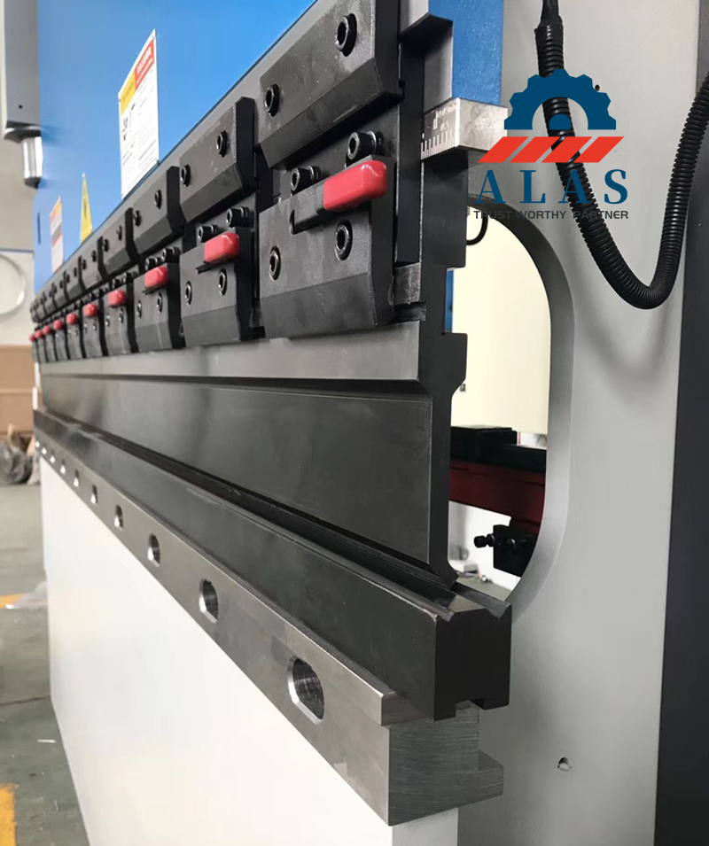
Heavy duty sectional top punch and precision ground single V bottom die for hydraulic press brake machines

4. Heavy-Duty Tool Specification Comparison

To help engineering teams select accurate, application-specific tooling grades efficiently, the following table systematically compares the precision performance and structural differences between conventional standard tooling, mainstream regional heavy series tooling, and ALAS reinforced high-tonnage dedicated tooling:
Technical Parameter
EU Standard Bending Tooling
North American Heavy Series
ALAS Heavy-Duty / High-Tonnage Dies
Punch Profile Type
Segmented 90°/88° sharp tip
One-piece 3/4-inch heavy keyway shank
Reinforced Gooseneck / Straight Punch
Lower Die V-Opening (mm)
6 / 8 / 12 / 16 / 20 / 25 / 32 / 40 / 50
0.50" to 3.0" (12.7mm to 76.2mm)
60mm up to 250mm+ (Equipped with heavy multi-V and adjustable block options)
Angular Tolerance
±0.2°
±0.3°
Strictly within ±0.15° or better
Surface Hardness (HRC)
50–52 HRC (0.2mm nitrided depth)
48–50 HRC (Standard induction hardening)
54–56 HRC (Deep-layer ion nitriding + anti-galling coating)
Standard Segment Length
835mm / 415mm standard split size
Single solid piece up to 3050mm
Modular configurations assembled up to 4000mm – 6000mm+
Max Applicable Plate Thickness
0.5 mm – 12.0 mm
0.8 mm – 16.0 mm
6.0mm up to 25.0mm+ high-tensile steel
Rated Tonnage Capacity
Max 100 Tons / Meter
Max 120 Tons / Meter
Heavy load rated: 150T/m up to 250T/m+

Practical Empirical Engineering Formulas

For reliable and safe thick-plate bending setup on hydraulic press brakes, the following specialized empirical formulas prevent over-tonnage risks, avoid tool damage, and ensure precise forming results:

1. Heavy Plate V-Groove Selection Rule

Conventional thin-sheet V-groove multiplication standards are not applicable to high-tonnage thick-plate bending. For structural heavy steel processing, follow the dedicated engineering baseline:

V ≈ (10 ~ 12) × T

  • V = Bottom Die V-Groove Opening Width (mm)

  • T = Heavy Workpiece Material Thickness (mm)


Note: For high-tonnage heavy bending (thickness T ≥ 6mm), scaling up the lower V-die opening to 10–12 times the material thickness is highly recommended to drastically lower the required hydraulic tonnage and prevent unexpected die shoulder chipping.

2. Advanced Bending Force Formula for High-Strength & Armored Plates

For high-yield-strength alloys including Hardox, Weldox, and heavy-gauge stainless steel, the standard bending force formula cannot deliver accurate results. Use this optimized calculation formula for high-precision tonnage calibration:
P = (1.42 × σb × t² × L) ÷ V
  • P = Required Bending Force (Tonnage) in kilonewtons (kN)

  • σb = Ultimate Tensile Strength of the target material (MPa)

  • t = Thick workpiece plate thickness (mm)

  • L = Effective plate bending length (mm)

  • V = Bottom die V-opening width (mm)

Engineering Guidance: This specialized formula is vital when calculating forming tonnages for high-yield metals such as stainless steel (SUS304/316) and armored wear plates (e.g., Hardox grades). Since these materials possess significantly higher tensile strength (σb) than mild steel, accurate pressure forecasting prevents accidental over-tonnage damage to both the machine ram and lower V-die blocks.


Technical engineering drawing showing cross section dimensions of a press brake top punch and 4-way multi-V bottom die

5. Heavy-Duty Die Classification & 5-Step Engineering Selection Guide

Classification by Structural Upper Punch Profile

Heavy-duty press brake punches feature differentiated structural designs for distinct forming scenarios, covering standard right-angle bending, deep groove forming, radius profiling and custom complex shaping:
Heavy-Duty Straight Punches: Equipped with reinforced shanks and widened load-bearing shoulders, these standard punches serve as the mainstream solution for high-tonnage bending of conventional 90° structural right-angle profiles, delivering stable rigidity for daily heavy plate processing.
Acute/Sharp Angle Heavy Punches: Engineered with precision tight angles (30°, 45°, 60°), these tools support deep small-angle bending. They provide powerful springback compensation specifically for high-yield-strength steel plates to guarantee accurate final forming angles.
Reinforced Gooseneck Punches: Designed with an optimized deep-clearance throat structure, these punches effectively avoid sidewall collision and interference during multi-stage processing and deep U-channel heavy bending, catering to deep forming requirements for thick structural parts.
Heavy Radius Punches (R-Tools): Configured with large-size cylindrical nose radii (R10, R20, R50 and above), they disperse concentrated local bending stress. This design prevents plate cracking and reduces surface scratches, ideal for high-quality forming of critical structural steel components.
Bespoke Non-Standard Punches: Developed via professional 3D CAD modeling and DFM reverse engineering, fully customized punch structures adapt to complex multi-stage forming geometries and special heavy-duty manufacturing requirements that standard tooling cannot meet.

Classification by Workpiece Material Processing Intensity

Tooling is professionally categorized based on material hardness, tensile strength and processing load to match different heavy-duty working conditions:
High-Strength Special Dies: Forged from deep-hardened, high-toughness core alloy steel, these dies are specially engineered to withstand extreme crushing pressure during bending. They are applicable to stainless steel, ultra-high-tensile alloys, Hardox wear-resistant steel and armored steel plates with rigorous processing demands.
Heavy-Duty Multi-V & Adjustable Blocks: Built for high versatility in heavy steel fabrication workshops, these modular lower dies support rapid switching of large V-opening sizes. They efficiently adapt to the bending and forming of various hot-rolled structural steel plates, improving overall production flexibility.

The 5-Step Professional Selection Process for Heavy-Duty Tooling

This standardized engineering selection workflow eliminates tool mismatch, over-tonnage risks and forming inaccuracies, providing reliable tooling configuration solutions for thick-plate and high-strength steel bending:

Step 1: Analyze Material Yield Strength & Calibrate Rebound Angle

Structural mild steel features low elastic recovery. Adopt 86°–88° upper punches to obtain precise 90° finished bending angles. In contrast, heavy stainless steel and high-tensile alloy plates generate significant angular springback. For such materials, select acute-angle punches (75°–80° or customized smaller angles) to implement over-bending compensation and offset springback deviation.

Step 2: Apply the Scaled Thickness Rule for Large V-Groove Openings

Improper V-slot matching under high tonnage directly causes shoulder cracking and premature tool failure. Follow the classified scaled V-opening standards for thick plates:
Medium Structural Plates (3mm ≤ T ≤ 8mm): Adopt V = 8 × T, balancing machine tonnage load and smooth inner bend radius for qualified conventional bending.
Heavy Infrastructure Plates (8mm < T ≤ 16mm): Adopt V = 10 × T, reducing stress accumulation on lower die shoulders and lowering local bending resistance to protect tool structures.
Ultra-Thick Steel Armor (T > 16mm): Adopt V = 12 × T to 14 × T, drastically cutting extreme forming tonnage and completely avoiding structural chipping and fracture of heavy-duty dies.

Step 3: Verify Structural Load Capacities & Safety Margins

Ensure the calculated active pressure never exceeds the rated capacity (Tons/Meter) of the selected tooling. A minimum 15% safety margin must be maintained for high-tensile material applications to prevent localized tool deformation.

Step 4: Align Punch Geometry with Finished Structural Part Profile

Match the upper punch type according to workpiece forming requirements and structural profiles: deploy heavy straight punches for standard structural channel bending, acute-angle tips for narrow tight folds, reinforced gooseneck punches for deep industrial enclosure forming, and heavy radius tool inserts for safety-critical curved structural components.

Step 5: Validate Heavy Machine Clamping & Interoperability Specs

Comprehensively check the parameters of the press brake’s upper ram and lower bed before tool installation. Confirm the equipment’s clamping standard (Amada heavy-duty, Wila hydraulic, Trumpf new standard, American large keyway shank, etc.), maximum open height and stroke range. This avoids tool-machine configuration mismatch and ensures seamless installation and stable high-load operation.

Precision top punch and bottom die installed on a hydraulic press brake machine with a quick clamping system

6. 6-Step Precision Installation & Structural Calibration for Heavy Tooling

Strict and standardized installation procedures are essential for high-tonnage tooling deployment. These rigorous protocols maximize on-site operational safety, minimize mechanical frame deflection during heavy loading, and sustain long-term bending angular stability and consistency in mass production. The following professional 6-step calibration procedure is tailored exclusively for heavy-duty press brake tooling assembly and commissioning:

Step 1: System Power-Down & Thorough Pre-Mounting Decontamination

Before any tool disassembly and mounting operations, fully cut off the machine’s power supply, shut down the main hydraulic pump, and completely depressurize all hydraulic accumulators to eliminate residual hydraulic pressure risks. Remove the existing old tooling assemblies safely. Use high-efficiency industrial cleaning solvents to thoroughly clean the upper clamping grooves, lower machine bed surface, and positioning keyways. Completely remove accumulated carbon scale, tiny burrs, and metal abrasive dust to ensure flat, fully fitted tool mounting surfaces and avoid assembly gaps that affect bending accuracy.

Step 2: Upper Heavy Punch Alignment & High-Pressure Hydraulic Locking

When installing heavy segmented punches, arrange each module symmetrically starting from the center of the machine ram toward both sides to ensure even tonnage distribution and balanced stress. Insert the precision-machined punch shanks completely into the clamping base, ensuring full close contact with the load-bearing shoulder surfaces. Activate the hydraulic clamping system and lock it at the standard working pressure (280 bar to 320 bar for heavy-duty tooling). Use a dial indicator or laser alignment instrument to detect straightness, controlling the upper punch linear straightness strictly within 0.05mm per meter.

Step 3: Lower V-Block Die Centralization & Axial Fastening

Use a professional crane or safety hoist to steadily place the heavy multi-V die or adjustable lower die block on the machine’s lower bed. Perform preliminary positioning to align the longitudinal centerline of the lower V-groove with the vertical movement centerline of the upper punch. Tighten the heavy-duty positioning guide rails and axial fixing bolts in sequence to fix the lower die firmly. This precise centering design eliminates torsional and eccentric shear force generated during high-tonnage bending, preventing tool deviation and structural damage.

Step 4: Micro-Inching Stroke Adjustment & CNC Backgauge Synchronization

Switch the press brake controller to manual “Jog/Inch” mode. Slowly lower the upper ram in micro-inching increments, guiding the punch nose into the lower V-groove until reaching a penetration depth of approximately 3.0mm. Conduct multi-point inspection to confirm uniform clearance between punch sidewalls and V-die shoulders across the full tool length. Input calibrated thick-plate springback compensation values and precise positional parameters into the CNC backgauge system to complete synchronous positioning calibration.

Step 5: High-Tonnage Test Bending & Multi-Point Angular Correction

Perform trial bending using scrap workpieces that match the exact thickness and tensile strength of formal production materials. Measure the forming angle at both ends and the midpoint with a calibrated digital protractor. If minor angular deviation occurs due to machine frame deflection, fine-tune the CNC crown compensation system or add micron-level precision shims under the lower die base. Ensure the full-length angular tolerance of finished bending workpieces is strictly controlled within ±0.3°.

Step 6: Extreme-Pressure (EP) Lubrication & Continuous Lifecycle Maintenance Logging

Apply high-performance MoS2 (Molybdenum Disulfide) extreme-pressure lubricant to all contact surfaces including the punch nose radius and lower V-groove shoulders. This effectively reduces high-load friction and eliminates tool galling and workpiece scratching. Record all calibration parameters, batch material specifications and actual working tonnage in the equipment maintenance file. Conduct comprehensive visual inspections for eccentric wear, surface micro-cracks and fatigue stress marks every 5,000 continuous bending cycles to achieve full-lifecycle tool condition monitoring.

Export standard wooden box packaging for heavy duty press brake dies and shear blades to ensure anti-rust and safe transport

7. Heavy-Duty Press Brake Tooling: Frequently Asked Questions

This chapter answers core engineering and procurement questions regarding heavy-duty tool selection, compatibility, service life and customization, providing practical on-site guidance for production and technical teams.

Q1: How do we select the optimal V-groove opening for heavy plates to prevent tool damage?

A1: For thick structural steel plate bending, follow the fixed baseline standard: V-groove opening width = 10–12 × plate thickness (T). For instance, bending 12mm-thick structural steel requires V120 or V140 lower die grooves. Adopting undersized grooves (e.g., conventional V80) will sharply spike instantaneous bending tonnage, directly causing lower die shoulder chipping, severe workpiece edge cracking and irreversible angular forming deviation.

Q2: Can European Style heavy-duty tooling be retrofitted onto American Standard press brakes?

A2: Direct interchangeable installation is not feasible due to fundamental differences in shank structural geometry. European standard tooling adopts a 42mm unified tang structure, while American standard tooling features 1/2-inch or 3/4-inch keyway shank designs. To achieve cross-standard compatibility without replacing the machine ram, ALAS provides high-strength customized tool adapters and conversion clamping blocks, enabling mixed deployment of multi-standard tooling on a single press brake device.

Q3: What is the expected service life of a heavy-duty nitrided 42CrMo die under high tonnage?

A3: With standard load conditions and standardized MoS2 extreme-pressure lubrication maintenance, ALAS precision-ground and deep ion-nitrided 42CrMo dies achieve a service life of 800,000 to 1,000,000 continuous bending cycles. Timely precision regrinding is strongly recommended once abnormal conditions occur, including persistent workpiece burrs, overall angular deviation exceeding ±0.5°, and obvious abrasive indentation on V-groove curved surfaces.

Q4: Does ALAS provide customized non-standard tooling for complex heavy fabrication?

A4: Yes. ALAS specializes in non-standard heavy-duty tooling customization, covering heavy radius punches, oversized multi-V adjustable dies, special offset dies and various complex profile tools manufactured strictly according to customer CAD drawings. The professional DFM engineering team completes blueprint review within 24 hours, supported by 3D scanning reverse engineering technology. The conventional custom production cycle is 10–15 working days.

Q5: Why is 42CrMo preferred over T8/T10 carbon steel for high-tonnage metal forming?

A5: High-tonnage bending generates complex multi-directional tension and compression stress. As a premium chromium-molybdenum alloy steel, 42CrMo (AISI 4140) delivers excellent deep hardenability, structural toughness and anti-fatigue performance. Although T8 and T10 carbon steels offer basic surface hardness, their brittle core structure is prone to sudden fracture and edge collapse under extreme local pressure. With precision edge induction hardening treatment, 42CrMo has become the globally recognized standard material for safe and stable heavy-duty steel fabrication.

8. International Compliance, Field Case Studies & Metallurgical Standards

All ALAS heavy-duty tooling manufacturing processes comply with DIN 55271 and ASTM E290-22 international industrial specifications. Overall structural machining tolerances adhere to ISO 2768-mK standards, with cross-sectional bending clearance variation strictly controlled below 0.5% of workpiece plate thickness, ensuring standardized and reliable product quality.

Real-World Heavy Industrial Case Studies

Case Study 1: Multi-V Variable Die Upgrade for a Philippine Heavy Machinery Plant

The Challenge: The client traditionally adopted single-V integral solid dies to process excavator and dump truck heavy chassis components. Frequent tool replacement required crane assistance, resulting in prolonged equipment downtime, low production efficiency and potential operational safety hazards.
The ALAS Solution: ALAS customized and installed integrated heavy-duty multi-V adjustable base blocks. Operators can quickly switch V-opening specifications from V60 to V200 by adjusting precision spacer shims, eliminating the need for integral die disassembly and replacement.
The Results: The workshop product reject rate dropped from 4.2% to 0.9%, tool changeover time was reduced by 70%, and the overall daily production efficiency of the production line increased by 45%.

Case Study 2: Structural Steel Fabrication Upgrade for Jiangsu Infrastructure Project

The Challenge: When bending 3000mm-long and 16mm-thick bridge structural steel plates, the equipment suffered from obvious frame deflection and inconsistent full-length bending angles, failing to meet infrastructure engineering precision requirements.
The ALAS Solution: Upgraded to ALAS high-precision segmented 42CrMo heavy punches, matched with professional mechanical deflection compensation crown rail systems to eliminate frame deformation errors.
The Results: Average tool setting and replacement time was shortened from 18 minutes to 6 minutes. The full-length bending angular accuracy of 3-meter-long workpieces was stably controlled within ±0.25%, and the annual tool maintenance cost was reduced by 48%.

42CrMo / AISI 4140 International Material Equivalence Matrix

To facilitate international engineering procurement and technical docking, the following table sorts out the authoritative equivalent grades of 42CrMo tool steel under global mainstream standards:
Country / Standard Organization
Reference Authority Code
Equivalent Metallurgical Material Grade
China (GB)
GB/T 3077
42CrMo / 42CrMo4
United States (AISI / ASTM)
ASTM A29
4140 / G41400
International Standardization
ISO 683-1
42CrMo4
Germany / Europe (DIN EN)
DIN EN 10083
1.7225 / 42CrMo4
Japan (JIS)
JIS G4105
SCM440 / SCM440H
United Kingdom (BS)
BS 970
708M40 / EN19

Industrial surface grinding process for 42CrMo press brake punch with continuous cooling system at ALAS factory

Precision milling process of a heavy duty double V bottom die block for press brake machines in the ALAS workshop

Previous: 
Next: 
ALAS - Trust-Worthy Industrial Machinery Tooling Partner Logo
Phone:
86-15852949220
Address:
Jiangning District, Nanjing
About Us

Nanjing Alas International Co., Ltd. is a professional industrial tooling manufacturer focused on shear blades, bending dies, shredder blades, and custom wear parts. We offer full application engineering, material selection, setup guidance, and after-sales support to global customers.
Tell us your requirements, and our engineering team will provide professional solutions for blade specification, tool life optimization, and cost-effective production.

Subscribe
Sign up for our newsletter to receive the latest news.
Copyright © 2021-2026 NANJING ALAS INTERNATIONAL CO., LTD 苏ICP备2021025144