

Phone:
86-15852949220


Views: 21 Author: Site Editor Publish Time: 2026-01-24 Origin: Site
[Hardness >60 HRC] ──► Low Impact Toughness ──► Carbide Network Stress Concentration ──► Micro-Chipping

[Cyclic Load Pounding] ──► Residual Tension Accumulation ─────────────────────────────► Macro-Cleavage Failure
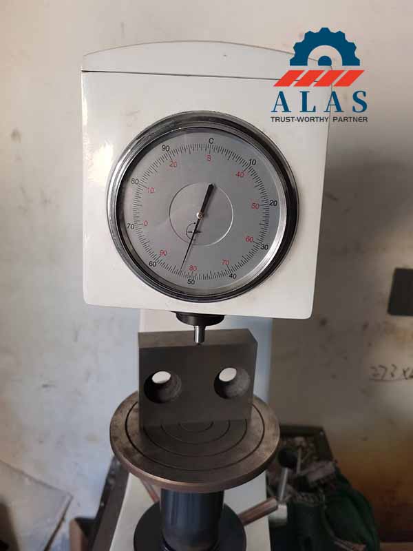
Industrial rebar cutting operates under cold shear kinematics, subjecting the component edge to immense instantaneous shock whenever meeting the irregular transverse herringbone or helical patterns of deformed steel reinforcement.
Pushing working hardness beyond 60 HRC drastically shrinks the material impact toughness envelope, shifting the failure mode from steady abrasive wear to catastrophic brittle cleavage fracture.
Under high-frequency cyclic loading, this kinetic impact initiates micro-cracking along the metallic grain boundaries. These micro-fractures propagate rapidly across the monolithic forging profile, transforming into macro-chipping or sudden cleavage failure under full mechanical load components.
Utilizing hot-work alloy tool steels like H13 in cold shearing operations requires specific tempering selection to bypass internal embrittlement zones and eliminate residual structural tension.
Workshops blindly chasing high working hardness lock the material inside its lowest impact toughness envelope, introducing severe risk of sudden brittle cleavage under high cyclic force.
To unlock elite fracture resistance and sustain high kinetic kinetic impact shock loads without cracking, the metallurgy must decrease working hardness strictly to 50 to 55 HRC.
This thermal modification transforms the underlying microstructure into tough, stress-relieved tempered martensite, providing true mechanical shock absorption across the monolithic forging profile
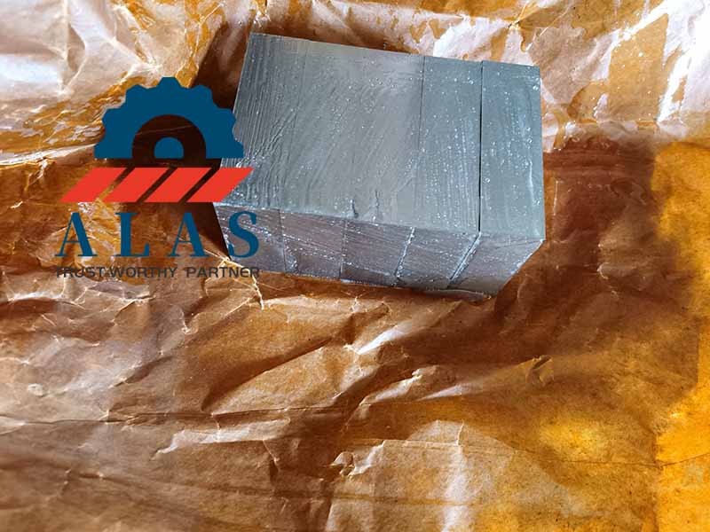
High-carbon high-chromium tool steels such as Cr12MoV provide elite abrasive wear defense at 58 to 60 HRC but possess limited inherent toughness due to severe primary carbide segregation networks.
When processing thick feedstock or executing high-speed multi-bar cutting, these hard carbide networks act as structural stress concentration sites.
If structural shock loads exceed the lower matrix elasticity, the shearing edge chips unpredictably.
This structural limit restricts the safe application boundary of Cr12MoV strictly to a conservative maximum diameter of 32 mm or less under uniform, low-impact indoor automated factory processing lines. Processing extra-large structural bars above 32 mm up to 55 mm forces an immediate metallurgy upgrade to high-toughness forged H13.
[Grinding Variance Past ±0.1mm] ──► Holder Lateral Play ──► Movable Blade Out-of-Squareness ──► Corner Spalling

[Variable Clearance Gap]       ──► Incomplete Shear   ──► Material Wedging & Wrapping      ──► Block Shattering
Finish grinding thickness tolerance limits direct the structural stability of the shear block inside the machine assembly slot.
Finished thickness tolerance and linear parallelism must be held strictly within the manufacturing red line of ±0.1 mm to completely eliminate lateral play inside the machine holder slot during the shearing stroke.
Physical displacement deviating from this calibration window alters horizontal clearance gaps dynamically, forcing the traveling movable blade out of squareness, creating uneven axial bending stresses across the monolithic block profile, and inducing rapid corner spalling.
The fixed horizontal blade side gap must align tightly under non-overlapping boundaries to distribute shear stress evenly.
Configuring a loose or variable gap causes incomplete material shearing, forcing the reinforcement bar to wedge between the components.
This material wrapping imposes immense lateral force onto the tool seats, destroying internal machine bearings and causing catastrophic block shattering under full machinery tonnage.
Grinding replacement cutting blocks to a razor-sharp edge creates an extremely fragile geometric profile vulnerable to instant fracturing under cyclic load components.
Mechanical stress concentrates tightly at the absolute tip during metal-to-metal contact.
Without a designated mechanical transition chamfer, the brittle edge cannot withstand the periodic pounding of deformed reinforcing bars.
                  SIDE CLEARANCE GAP NON-OVERLAPPING BOUNDARIES

      FEEDSTOCK DIAMETER                  REQUIRED SIDE CLEARANCE GAP
   ┌───────────────────────────┐         ┌───────────────────────────┐
   │ Ø6 mm – Ø20 mm            │ ──────► │ 0.3 mm  │
   ├───────────────────────────┤         ├───────────────────────────┤
   │ >20 mm – Ø32 mm           │ ──────► │ 0.4 mm  │
   ├───────────────────────────┤         ├───────────────────────────┤
   │ >32 mm – Ø55 mm           │ ──────► │ 0.5 mm  │
   └───────────────────────────┘         └───────────────────────────┘
Ø6 mm to 20 mm Reinforcement: Requires a side clearance gap dead-locked exactly at 0.3 mm.
>20 mm to 32 mm Reinforcement: Requires a side clearance gap dead-locked exactly at 0.4 mm.
>32 mm to 55 mm Reinforcement: Requires a side clearance gap dead-locked exactly at 0.5 mm.
Production line supervisors must audit and log horizontal side clearances using precision feeler gauges before every manufacturing shift.
Adjust lateral gaps strictly based on processing diameter boundaries to maintain shearing efficiency and avoid structural binding:
For Ø6 mm to 20 mm reinforcement, fix the horizontal gap exactly at 0.3 mm.
For >20 mm to 32 mm reinforcement, fix the horizontal gap exactly at 0.4 mm.
For >32 mm to 55 mm reinforcement, fix the horizontal gap exactly at 0.5 mm.
Shop floor grinding technicians must never leave primary shearing edges completely sharp after reconditioning.
Maintenance personnel must execute a uniform transition chamfer measuring 0.1 mm to 0.2 mm at a 45-degree angle along the working edge.
This geometric modification successfully disperses instantaneous kinetic energy across the underlying matrix mass, suppressing stress concentration and preventing microstructural edge spalling.
Workshops must implement a data-driven preventative tool rotation schedule mapped against logged stroke cycles rather than running blocks to failure.
Technicians must index and rotate the four-sided square tool block exactly every 1,000 cuts on high-frequency automatic lines, or the moment physical wear lands reach 0.6 mm, or when processing causes visible structural burrs deeper than 0.3 mm.
Acoustic monitoring must be deployed; deep metallic squealing or dragging signals advanced abrasive depletion demanding immediate rotation.
Replacing fixed and movable elements concurrently as a matched single pair guarantees uniform wear alignment, preserves a strict end-face shear inclination deviation within 1.5 degrees, and successfully maximizes relative line OEE.
Nanjing Alas International Co., Ltd. is a professional industrial tooling manufacturer focused on shear blades, bending dies, shredder blades, and custom wear parts. We offer full application engineering, material selection, setup guidance, and after-sales support to global customers.
Tell us your requirements, and our engineering team will provide professional solutions for blade specification, tool life optimization, and cost-effective production.